20.25H.130 Performance standards – Coal mine hazard area.
The requirements of this section may not be modified through a critical areas report.
A. Application of Regulation and Disclosure on Plats.
1. The subdivision or development of land potentially affected by abandoned coal mines, as described in these regulations or as designated on the Coal Mine Area (CMA) Map, or the Coal Seams Map, maintained by the Development Services Department (DSD), shall be subject to the requirements of this section. Development includes construction of buildings, utilities, and other infrastructure as defined in subsection B of this section. The requirements of this section are in addition to other pertinent City of Bellevue requirements.
Exceptions:
a. Additions to existing single-family residences, in CMS Zone 1, that were not originally subject to this section, are exempted as follows:
i. Additions of 500 square feet or less of new covered floor area are completely exempted.
ii. Additions and replacements which are less than 50 percent of the total proposed floor area are exempted, except for subsections I.1.e, I.4.c, I.4.d, and I.4.e of this section.
b. Detached uninhabited structures less than 500 square feet in CMS Zone 1, which are accessory to single-family residences and on the same property, are completely exempted.
2. Any subdivision or short subdivision that includes property designated as within a CMS Zone shall disclose the designation on the face of the plat and shall include a reference to the requirements of this section.
B. Definitions. For purposes of this section only, the following defined terms apply:
1. “Angle of draw” (also termed “limit angle”) means the angle of inclination from the vertical of the line connecting the edge of the coal mine workings with the outer limit of the trough subsidence area. For inclined coal seams (such as those in the Coal Creek area), downdip and updip limit angles (which in general will not be identical) are defined at the downdip and updip limits of the coal mine workings, respectively. See Figure 1.
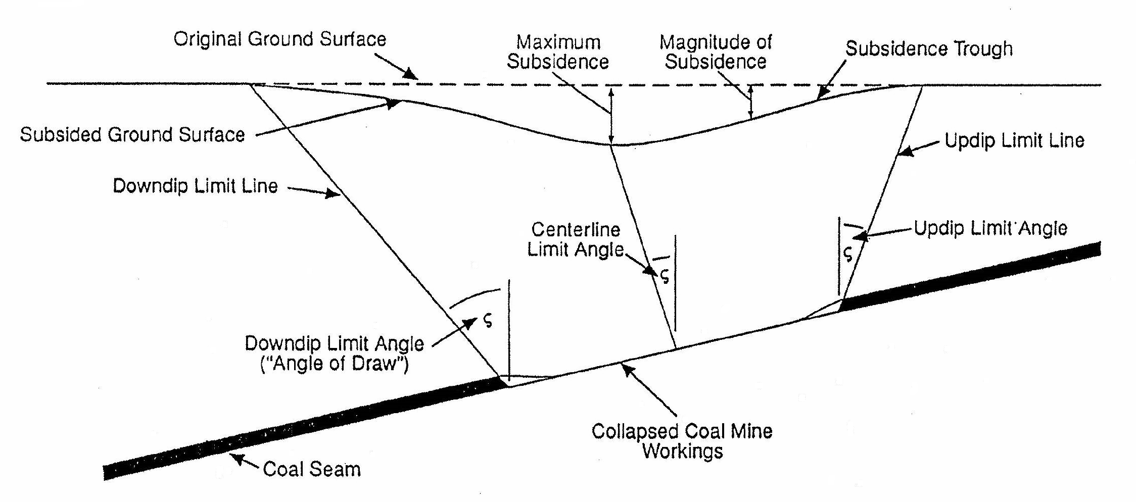
Figure 1.
2. “Coal Mine Subsidence (CMS) Zones” means areas where there is a potential for future trough subsidence or sinkhole development due to collapse of abandoned coal mines as delineated on the Coal Mine Area (CMA) Map.
3. “Coal Mine Area (CMA) Map” means a map (Exhibit A attached to the ordinance codified in this chapter) delineating zones of possible mine subsidence and hazards due to abandoned coal mines based on calculated potential surface strains and tilts, and documented possible coal mine hazards.
4. Coal Mine Waste Dump. Also termed “spoil piles,” “coal mine waste dumps” are a loose-dumped mix of soil, rock, coal and any other materials that are produced as a waste product during mining.
5. “Development” means any structure, habitable or nonhabitable, or other modification of the natural landscape above and below ground or water.
6. “Extraction ratio” means ratio or percentage of extracted coal relative to total coal in a given area of a seam.
7. “Gas emissions” means explosive, poisonous, or suffocating gases emitted from coal seams.
8. “Lithology” means type of rock, such as sandstone, siltstone, or shale.
9. Limit Angle. See “angle of draw.”
10. “Mine hazard” means any hazard associated with abandoned coal mines or prospects including but not limited to trough subsidence, coal mine waste dumps, and public safety mine hazards such as sinkholes and shafts.
11. “Mine subsidence” means lowering of the ground surface, with resulting tilts and strains, due to movement of the underlying soil and/or rock into a void resulting from an underground mine or mine entry.
12. “Outcrop” means the exposure of bedrock or strata projecting through the overlying soil cover.
13. “Panel” means the area of a seam from which coal has been systematically extracted.
14. “Prospect” means an excavation used for exploration or sampling of coal seam.
15. “Public safety mine hazards” means mine hazards that may constitute a danger to public safety, including sinkholes, shafts, mine entries, slope entries, gas emissions, mine fires, and others identified as a public safety hazard by a qualified engineer or geologist.
16. “Qualified engineer or geologist” means a Washington State registered geotechnical (civil branch) or mining engineer, or an engineering geologist, who is experienced in evaluation of coal mine subsidence and coal mine hazards, and who is accepted by the City of Bellevue to undertake such evaluations for projects regulated by the City of Bellevue; engineers or geologists without such experience may not be considered to be qualified.
17. “Remaining mine height” means current true thickness (measured perpendicular to the seam) of cumulative voids in and above mine workings which corresponds approximately to the original coal seam thickness less the subsidence that has already occurred at depth.
18. “Seam” means a stratum or bed of coal or other mineral. Individual coal seams in the Coal Creek area are generally identified by name, such as the Primrose, Jones, and Muldoon seams.
19. “Shaft” means a vertical or inclined tunnel for access to, or ventilation of, mine workings.
20. “Sinkhole” means a type of subsidence consisting of collapse of the ground surface into an underground void in which the surface expression has a characteristic funnel or shaft shape. Also referred to as a “collapse pit.” See Figure 2.
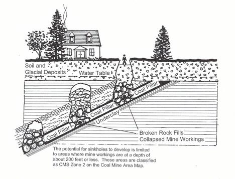
Figure 2.
21. “Slope entry” means a mine entry where the mine access tunnel is inclined to horizontal or sloped.
22. “Sphere of influence” means the City of Bellevue’s potential annexation area based on an agreement among the cities of Bellevue, Renton and lssaquah.
23. Spoil Pile. See “coal mine waste dump.”
24. “Strain” means change in length per unit length, e.g., a change in length of 0.1 feet over a 100-foot length corresponds to a strain of 0.001.
25. “Subcrop” means location of strata such as a coal seam beneath an overlying soil cover.
26. “Subsidence factor” means the ratio of maximum surface subsidence to extracted coal seam thickness.
27. “Tilt” means differential settlement per unit length, e.g., a tilt of one in 500 corresponds to a differential settlement of 0.2 feet over a length of 100 feet.
28. “Trough subsidence” (also termed “regional downwarping”) means a surface depression caused by mine subsidence that is generally characterized by a gentle and continuous dish shape that extends beyond the vertical projections of the limits of mining within the seam. See Figure 1.
C. Overview of Coal Mine Subsidence (CMS) Zones. The Coal Mine Area (CMA) Map delineates areas within the City of Bellevue and associated potential annexation area (sphere of influence) that could be affected by subsidence of abandoned coal mines. The CMA Map defines and identifies Coal Mine Subsidence (CMS) Zones based on potential surface tilts and strains and whether there is a potential for sinkhole development.
The CMS Zones have been developed based on generalized evaluation of available mine maps and records. Direct subsurface information (boring data) on the condition of the mine workings was not available for development of these zones and regulations except for the Newcastle-King Mine. This Newcastle-King Mine information was used to evaluate potential coal mine impacts associated with the existing plat of The Woods. Alternative interpretations of potential subsidence effects could result from site-specific evaluation and analysis based on detailed review of historic data, direct subsurface information, or alternative assumptions.
A surface reconnaissance report and site-specific evaluations are required prior to permitting subdivision or development on any site in a CMS Zone. Methods of analysis shall be described as appropriate. Construction will be permitted in any CMS Zone after elimination of risk to public safety associated with abandoned coal mines, and mitigation of coal mine waste dumps (if any) and potential trough subsidence.
1. CMS Zone 1. Strain exceeds 0.003.
Tilt exceeds 1:350.
Construction is permitted only after a site-specific evaluation of potential trough subsidence and incorporation of appropriate mitigation measures.
Site-specific structural and civil design is required in all areas per subsections I and J of this section.
2. CMS Zone 2. Areas directly underlain by coal mine workings at a depth of 200 feet or less, documented prospects and areas within 100 feet of such areas.
There is a potential for sinkhole development, or for other public safety mine hazards. Construction is permitted only after potential public safety mine hazards are investigated and eliminated. A direct subsurface investigation program is required to investigate potential sinkhole development. In addition, if any mine workings could potentially cause trough subsidence at the site, construction is permitted only after a site-specific evaluation of potential trough subsidence and incorporation of project-specific mitigation measures as required for CMS Zone 1.
3. Areas of Potential Undocumented Workings. CMS Zones are based on an evaluation of documented workings. There is, however, some potential for undocumented workings to exist in the vicinity of outcropping or subcropping seams. The potential for undocumented workings must be evaluated for any property within 100 feet of the subcrop lines of the Jones and Primrose seams between and beyond known coal mine workings, except for construction of attached additions to, or miscellaneous structures accessory to and within 50 feet of, existing residential buildings. The subcrop lines indicating those areas of potential undocumented workings are shown on the Coal Seams Map.
Note: The Primrose seam subcrop through the plats of Forest Ridge Estates Divisions I and II, The Woods, and Forest Park No. 4 has not been shown on the Coal Seams Map because geotechnical exploration and abandoned mine hazard assessments were completed and accepted by the City at the time these plats were developed. Therefore, as no undocumented workings were found by those investigations and subsequent development, the Primrose seam subcrop through those plats has not been shown on the Coal Seams Map so that it is clear that future building permit applications for lots in those plats are not subject to these regulations.
4. Changing a CMS Zone Designation. The CMS Zone designation for a property in CMS Zone 1 may be removed if it is demonstrated by site-specific evaluation of trough subsidence that magnitudes of potential surface strains and tilts at the property are less than the levels specified above.
The site-specific evaluation of trough subsidence shall be completed by a qualified engineer or geologist and shall be performed in accordance with the requirements of these regulations. The same or similar assumptions as were used in developing these regulations and the CMA Map shall be used when undertaking the site-specific evaluation of trough subsidence. If the evaluation results in a proposed change to the CMS Zone designation based on additional information identified from mine records, or new information available from direct investigation of subsurface conditions by drilling or other means, then the engineer shall be required to demonstrate that the tilts and strains calculated represent the maximum tilts and strains at the site for all possible time sequences of mine collapse.
A CMS Zone 2 designation may be changed to a Zone 1 designation if a direct subsurface investigation demonstrates the absence of coal mine workings or that the coal mine workings, if present, are in a fully collapsed condition.
Any change in a CMS Zone designation must be accepted by the Director of the Development Services Department or his or her designee.
D. Application/Pre-Permit Issuance Requirements.
1. General Requirements. A surface reconnaissance shall be undertaken for the CMS Zones and for areas of potential undocumented workings. All surface reconnaissance and evaluation of coal mine hazards and potential trough subsidence shall be performed by, or under the direct supervision of, a qualified engineer or geologist.
2. CMS Zone 1. Applicants shall:
a. Conduct a surface reconnaissance and submit at application a report identifying any public safety mine hazards, coal mine waste dumps, or evidence of mine subsidence.
b. If hazards other than trough subsidence are identified in the surface reconnaissance reports, mitigate the hazards after acceptance of an evaluation and remediation plan by DSD.
c. Conduct a site-specific evaluation of potential trough subsidence.
d. Mitigate for trough subsidence including future surface settlements above collapsed mine workings by developing site-specific design that can accommodate calculated potential subsidence effects.
3. OMS Zone 2. Applicants shall:
a. Conduct a surface reconnaissance and submit at application a report identifying all public safety mine hazards, coal mine waste dumps, and evidence of mine subsidence.
b. Conduct site-specific evaluation of potential for sinkhole development, including subsurface investigation. Test pits may be used to investigate coal mine waste dumps and other shallow hazards such as slope entry portals and shaft collar areas. Drilling is required for coal mine workings or other hazards that cannot be adequately investigated by investigations from surface. Drilling may demonstrate that there is no risk of sinkhole development due to the absence or fully collapsed condition of mine workings. Alternatively, drilling may document sinkhole risks, and the applicant must then design a mitigation program to eliminate all such risks.
c. Eliminate risk of sinkhole development and mitigate other public safety mine hazards and/or coal mine waste dumps after acceptance of an evaluation and remediation plan by DSD.
d. If the site could be subject to trough subsidence due to coal mine workings, conduct a site-specific evaluation of potential trough subsidence.
e. Mitigate for trough subsidence including future surface settlements above collapsed mine workings by developing site-specific design that can accommodate calculated potential subsidence effects as required for CMS Zone 1.
4. Areas of Potential Undocumented Workings. If the property lies within 100 feet of a coal seam outcrop or subcrop shown on the Coal Seams Map, but outside any CMS Zones, applicants shall (except as exempted under subsection C.3 of this section):
a. Conduct a surface reconnaissance and submit at application a report identifying any public safety mine hazards, coal mine waste dumps, or evidence of mine subsidence.
b. If hazards other than trough subsidence are identified in the surface reconnaissance report, mitigate the hazards after acceptance of an evaluation and remediation plan by the DCD.
5. Requirements for More Than One Zone. If a property lies within more than one CMS Zone and development will include construction of multiple structures, each structure shall be designed to meet the regulatory requirements for the zone in which the structure is located. Any structure except roads and utility lines that lies within more than one zone shall be designed in accordance with the requirements for the higher zone number. Roads and utility lines shall be designed in accordance with the requirements for each zone throughout the length of the facility located within that zone.
E. Surface Reconnaissance Reports. A surface reconnaissance shall be undertaken for all CMS Zones and for areas of potential undocumented workings.
The surface reconnaissance shall be undertaken following review of available geologic hazard maps, mine maps, mine hazard maps, and air photographs to identify any subsidence features or mine hazards including but not limited to surface depressions, sinkholes, mine shafts, mine entries, coal mine waste dumps, and any indication of combustion in underground workings or coal mine waste dumps that are present on or within 100 feet of the property. The surface reconnaissance shall include, but not be limited to, inspection, review, and documentation of any known hazards that have previously been documented by the Office of Surface Mining, Abandoned Mined Land Program (Skelly and Loy, 1985), or that have been identified from review and interpretation of air photographs or other sources.
The surface reconnaissance report shall include:
1. Historical mining data, including available copies of original mine records for mine workings in coal seams.
2. A map showing property boundaries, CMS Zone boundaries, and any potential hazards identified on or within 100 feet of the property.
3. If hazards are identified, a proposed program of detailed site investigation to support engineering design for remediation.
4. For sites in CMS Zone 2, proposed subsurface investigation program, including exploratory test pit and drill hole locations, and mine plans for all seams that lie within 200 feet of the ground surface.
For sites where trough subsidence must be calculated, the surface reconnaissance report may also include proposed site evaluation and trough subsidence calculation methodology; alternatively, that can be submitted in a separate report.
F. Remediation or Mitigation of Hazards Other Than Trough Subsidence. If hazards are identified in the surface reconnaissance report:
1. Include a separate section in the surface reconnaissance report that proposes a program of detailed site investigation to support engineering for remediation of the hazards.
2. Upon acceptance of the site investigation approach by the DSD, conduct the evaluation. Submit the results to the DSD along with a proposal for remediation design including the following types of mitigation:
a. Mine Entries and Shafts. Mine entries and shafts shall be permanently sealed using controlled backfill and/or grouting, or an approved, engineered seal. Acceptable seal construction consists of a tapered, reinforced concrete plug constructed within a steel form; a below grade reinforced concrete cap constructed over shaft collars; and a reinforced concrete plug for sealing horizontal mine entries.
Site preparation prior to installation of the plug shall include permanently diverting surface drainage away from the shaft or mine entry, and excavating loose rock and soil away from the collar of the shaft or the mine entry portal.
Shaft and slope entry seals shall be designed and installed so that they are bearing on competent bedrock or dense, competent till. The top of the tapered plug or the base of the cap shall extend a minimum of two feet in all directions beyond the shaft or slope entry. The length of any plug used to seal a horizontal mine entry shall not be less than the maximum dimension of the entry. The need for installing additional backfill behind the seal of a horizontal mine entry to prevent potential subsidence over the entry shall be determined on a case-by-case basis.
b. Existing Sinkholes and Shallow Prospect Excavations. Existing sinkholes and shallow prospect excavations shall be backfilled to surface using controlled placement of suitable backfill. Surface drainage shall be permanently diverted away from existing sinkholes and prospect excavations.
c. Potential Sinkholes. Demonstrate by direct subsurface investigation that coal mine workings either do not exist, or that the workings have fully collapsed so that there is no remaining potential for sinkhole development; or show that the hazards associated with any voids that are identified are fully mitigated by backfilling, grouting, or other approved means such that the potential for sinkhole development is eliminated.
A fence may be required to be constructed along the CMS Zone 2 boundary, or around known hazards, to prevent access to the area if the potential for sinkhole development has not been eliminated. If a fence is required, signs shall be posted on it, at intervals of no more than 100 feet, warning of danger due to possible sinkholes.
Any sinkholes that develop shall be promptly backfilled and surface drainage shall be diverted away from the sinkhole.
d. Coal Mine Waste Dumps. Any coal mine waste dump from which springs or seeps are discharging, or which shows evidence of seasonal discharge of springs or seeps, shall be removed or regarded to expose the source of the spring or seep.
Unless the stability of the coal mine waste dump is verified by a slope stability analysis meeting the requirements of the Minimum Standards for Slope Stability Analysis of the City of Bellevue Development Standards, the coal mine-waste dumps shall be removed from the site, or shall be regarded as necessary such that no slope in the coal waste material exceeds 2(H):1(V) and meets City of Bellevue stability criteria.
All coal mine waste material shall be covered with a minimum of two feet of clean soil and shall be revegetated in accordance with Chapter 23.76 BCC.
No construction shall be permitted over coal mine waste material unless a geotechnical investigation is completed by a soils engineer, and specific design and construction criteria are developed to mitigate the potential impacts of the coal mine waste on foundation stability and performance. Construction shall not be permitted within 100 feet of any coal mine waste dump that shows evidence of current or past combustion.
e. Mine Gases. Potential hazards associated with mine gases shall be mitigated by backfilling all mine entries, shafts, and sinkholes in accordance with this section.
f. Mine Fires. Construction shall not be permitted over workings where surface or subsurface investigations indicate the possible presence of combustion in the underlying seam or seams.
3. Once the proposed remediation approach is accepted by DSD, complete the engineering design drawings and specifications for the remediation. Upon acceptance by the DCD, complete the actual remediation.
4. Document the hazard mitigation by submitting as-builds and a remediation construction report. DSD must agree that hazards have been mitigated before any construction is allowed on the site.
5. Any public safety mine hazards shall be eliminated prior to any other development activities on the site. Hazard mitigation shall be performed by or under the direction of a qualified engineer or geologist. Any hazards found during any development activities shall be immediately reported to DSD.
6. No construction shall be allowed within 100 feet of an existing public safety mine hazard, regardless of whether the hazard is located on the property for which the permit application is being submitted or not. The decision on whether to permit construction directly over a public safety mine hazard that has been mitigated will be made on a case-by-case basis based on the type of mitigation and the proposed construction.
G. Site-Specific Evaluation – Potential Trough Subsidence.
1. Review of Available Records. The site-specific evaluation of potential trough subsidence shall include a detailed review of available copies of original mine records for mine workings in coal seams that could potentially influence the site by trough subsidence. The locations, depths, and thicknesses of such seams and workings shall be documented. Coal mine workings that could potentially influence the site shall be determined by projecting the downdip limit angle from the lowest limit of the documented workings to the ground surface. Mine workings are considered to potentially influence the property if the property lies within the line at which the limit angle intersects the ground surface.
2. Subsurface Investigations. Subsurface conditions may be evaluated by drilling. Although drilling is not compulsory, it is the most acceptable method for providing information that is acceptable for reducing the remaining mine height value used in subsidence calculations.
If the applicant wishes to conduct a subsurface investigation, the proposed approach must be submitted to DSD for review and acceptance.
Rotary drilling is an acceptable method of drilling, provided it is used in combination with downhole geophysical logging, including caliper logs. Core drilling is preferred, but is not compulsory, immediately above and through the predicted coal seam locations to facilitate interpretation of the condition of the mine workings. Rotary drillholes shall be logged continuously from 100 feet above to 20 feet below mine workings, including lithology at five-foot intervals, drill fluid circulation, penetration rate, and free fall of the drill string. Greater confidence will be placed in core drilling logs than rotary drilling logs.
As a guideline, it is recommended that a minimum of one drillhole penetrating each coal seam that could potentially cause trough subsidence at the site should be drilled for each 200-foot length of the south property boundary.
If a drillhole encounters solid or broken coal in an area that available mine maps indicates has been mined out, it shall be assumed that the true thickness of coal represents the thickness of intact or crushed pillars, and corresponds to the remaining mine height for calculating potential trough subsidence affects at surface. If the drillhole encounters voids at or above the location of the coal seam, the cumulative length of the voids shall be used to calculate the true cumulative thickness of the voids, which shall be taken to correspond to the remaining mine height. These assumptions can be modified based on additional drilling.
Direct evidence of the condition of panels in the same seam with similar dimensions, similar extraction ratios, and at a similar or shallower depth, shall be accepted as evidence of the condition of mine workings at any point.
Surface geophysics, or other indirect means, may be used to assist in projecting information between and beyond drillholes, but shall not be accepted as the sole method for evaluating the condition of underground mine workings and calculating remaining mine height. Assumptions concerning the extent of collapse of mine workings based on recorded extraction ratios shall be conservative because of possible inaccuracies of mine records, the likely presence of remnant pillars and the lack of data to accurately locate them, and because uncollapsed mine workings have been documented under similar conditions in King County.
3. Calculation of Trough Subsidence Magnitudes, Tilts, and Strains. Proposed calculation methods, design parameters, and assumptions that will be used shall be submitted for review and acceptance by the Director prior to calculating trough subsidence.
The recommended method for calculating potential trough subsidence magnitudes, strains, and tilts is the empirical function method of the British National Coal Board, as presented in their Subsidence Engineers’ Handbook, adjusted to reflect the effects of inclined seams and a downdip limit angle of 45 degrees. Recommended calculation procedures are detailed in subsection K.1 of this section.
Calculations shall be based on a conservative evaluation of site conditions developed from the review of available records, site investigation or other acceptable means, such as previous documentation by subsurface exploration of the condition of the coal seam(s) in the immediate vicinity of the site and at an equivalent depth below the ground surface. A subsidence factor of 0.5, a downdip limit angle of 45 degrees, and a value of remaining mine height equal to the seam thickness shall be used for the subsidence calculations unless direct field evidence or a review of detailed mine records is used to modify these values. The effects of individual panel widths and barrier pillar widths shall be considered in the calculation of potential tilts and strains. If direct subsurface investigation indicates that the mine workings are fully collapsed, an estimate of potential surface settlements due to consolidation of rubble and loose material shall be made for sites directly underlain by coal mine workings.
The subsidence analysis shall evaluate the cumulative effect of all seams that could induce trough subsidence at the site.
Alternative methods of calculating potential subsidence magnitudes, strains, and tilts may be used provided they incorporate similar assumptions to those specified in the preceding paragraphs. If alternative design parameters and assumptions are proposed, detailed justification must be provided to the DCD for consideration during their review and acceptance of the proposed calculation approach.
4. Documentation of Trough Subsidence Evaluation. The results of the detailed site evaluation shall be documented. Site plans shall be prepared showing the proposed development and calculated magnitudes of potential subsidence, strains, and tilts at the property boundaries and at the locations of any proposed structures. In addition, a map showing contours of potential subsidence magnitudes, strains, and tilts throughout the property shall be submitted for use in design of roads and utilities.
Appropriate recommendations shall be provided for structural and civil design requirements outlined in subsections I and J of this section, respectively.
H. Site-Specific Evaluation – Potential Sinkhole Development or Other Public Safety Mine Hazards.
1. Review of Available Record. To evaluate the potential for sinkholes in CMS Zone 2, the applicant’s qualified engineer or geologist shall first conduct a detailed review of available copies of the original mine records for mine workings that could potentially influence the property. Coal mine workings that could potentially influence the site shall be determined by projecting the downdip limit angle from the lowest limit of the documented workings to the ground surface. Mine workings are considered to potentially influence the property if the property lies within the line at which the limit angle intersects the ground surface. The locations, depths, and thicknesses of such seams shall be documented.
2. Proposed Site Investigation. Based on the review of available mine records, the qualified engineer or geologist shall then propose a site investigation program and submit it for review and acceptance by DSD as part of the surface reconnaissance report. The proposed program shall include the items and meet the requirements listed below:
a. Drillhole Locations. Subsurface conditions for coal seams located within 200 feet of the ground surface shall be investigated by drilling. Drillhole sites shall be selected at representative locations and at representative coal seam depths. Drillholes shall be located adjacent to, but not within, coal pillars that are shown on the mine plans. A minimum of five drillholes shall be drilled along the alignment of any linear structure, such as roads or utility lines designed to cross CMS Zone 2, or within the property boundary for other development of properties of five acres or less. The minimum number of drillholes for properties larger than five acres shall be one hole per acre or as determined by the Director.
b. Method of Drilling. Rotary drilling is an acceptable method of drilling provided it is used in combination with downhole geophysical logging, including caliper logs. Core drilling is preferred, but is not compulsory, immediately above and through the predicted coal seam locations to facilitate interpretation of the condition of the mine workings. Drillholes shall be logged continuously throughout their length, including lithology at five-foot intervals for rotary drillholes, drill fluid circulation, penetration rate, and free fall of the drill string. Greater confidence will be placed in core drilling logs than in rotary drilling logs; this may result in less drillholes being required if core drilling is used in the vicinity of coal seams instead of rotary drilling.
c. Shallow Public Safety Hazards. Shallow hazards such as slope entry portals, shaft collars, prospects and mine waste dumps may be investigated by test pits or trenching, providing the method enables investigation to an adequate depth for the hazard being investigated.
d. Any Other Site Investigation Techniques Proposed. Indirect means of subsurface evaluation, including geophysics, geologic projection, and evaluation of mining records, may be used to supplement drilling results, but shall not be used as the sole source for evaluating subsurface conditions prior to construction in Zone 2 areas.
3. Investigation Results and Interpretation. Once the Director has accepted the proposed site-evaluation, the applicant can proceed to the actual site investigation and must submit the results and the interpretation of those results to DSD.
The need for additional drilling shall be determined by the Director based on the results of the initial five drillholes. If a drillhole encounters solid or broken coal in an area that available mine maps indicate has been mined out, it shall be assumed that the true thickness of coal represents the thickness of intact or crushed pillars. If true coal thickness approximately corresponds to the original seam thickness, it shall be assumed that the mine workings have not collapsed. If the drillhole encounters a void at the location of the coal seam, the true length of the void shall be taken to correspond to the remaining mine height for evaluating the potential for sinkhole development. These assumptions can be modified based on additional drilling. If all drillholes verify that mine workings have effectively collapsed at all depths, further subsurface investigation shall not be required.
I. Mitigation of Trough Subsidence – Buildings in CMS Zone 1. These mitigation requirements apply to all new construction in CMS Zone 1, except as exempted by subsection A.1 of this section.
1. General Design Requirements.
a. Every building site shall be investigated by a qualified engineer or geologist who shall calculate tilts and strains, and determine appropriate design values for the building site.
b. The foundation elements of each building or structure shall be designed by a Washington State licensed structural engineer, with consideration of the subsidence effects anticipated at the site. The requirements of this subsection I are minimum standards. The structural engineer is responsible to ensure the adequacy of the foundation for the building or structure under consideration. The Building Official may accept alternate designs meeting the intent of these standards. Any portion of the building lateral system not meeting the conventional bracing requirements of the International Building Code, as adopted and amended by the City of Bellevue, must be designed by a structural engineer.
c. Building and structure foundations shall be designed for the loads and conditions specified in subsections I.2, I.3, and I.4 of this section in conjunction with all applicable loads stipulated in the International Building Code, as adopted and amended by the City of Bellevue. Vertical steps and horizontal offsets of footings and walls must be reinforced to meet the requirements of the International Building Code, as adopted and amended by the City of Bellevue, and the American Concrete Institute, to provide continuity of the reinforcement.
d. The forces generated by subsidence effects of tilt and strain shall be treated as live loads with the appropriate load factors and/or factors of safety in design. The friction drag force loads of subsection I.2 of this section must be combined simultaneously with the lateral earth pressure loads specified in subsection I.3 of this section, with both loads treated as earth pressure in load combinations. The subsection I.4.a, I.4.b, and I.4.d design requirements may be applied independently of the friction and earth pressure loads.
e. Utility lines shall not be rigidly connected to the foundation wall. A flexible joint shall be provided at the point of transition from soil support to building support for all utilities.
2. Design for Friction Force Loads.
a. CMS Zone 1 includes both tension and compression ground strain zones. Foundations and slabs on grade shall be designed to resist not less than the following ultimate friction forces for tension and/or compression as determined from the geotechnical investigation. Rigid crosstie struts may be used to reduce the span of foundation elements under horizontal load.
Fd = f(DL + 0.5 LL)
where Fd = Drag force parallel to ground strain direction
f = Ultimate coefficient of friction from soil to footing
DL = Design dead load
LL = Design live load (including snow load).
b. Isolated pad footings and posts shall be designed and constructed to ensure that the post remains plumb. This may be accomplished by reducing the friction under the footing, by rigid bracing of the post in each of four directions, or by other approved means. When post footings are incorporated into rigid crosstie struts, the struts must meet the requirements of subsection I.4.a of this section.
3. Design for Lateral Earth Pressure Loads.
a. Ultimate passive soil pressure shall be assumed to act on all vertical surfaces in contact with foundation soil due to horizontal strain occurring from a subsidence event. This applies to the horizontal projection of all below grade elements. These ultimate pressures, and the distribution, shall be determined by a qualified engineer or geologist in accordance with established engineering practice. Rigid crosstie struts may be used to reduce the span of foundation elements under horizontal load.
b. Where walls and footings are subject to compression zone forces, these lateral forces may be reduced by the use of compressible backfill material such as wood chips, shredded rubber, or other approved materials. If such a material is used, it is the responsibility of a qualified engineer or geologist to determine the appropriate design loads to be applied to the structure.
4. Design for Tilt and Curvature Conditions.
a. Foundations shall be rigid and shall be designed in accordance with standard engineering practices, but shall be able to resist as a minimum the shears and moments generated by (DL + 0.5 LL) on the support conditions specified in subsections I.4.a.i and I.4.a.ii of this section, where L is the total length of the building foundation in the direction under consideration.
i. An unsupported simple span length of eight feet or 0.4 L, whichever is less, anywhere within each segment of the foundation in each direction of the building.
ii. An unsupported cantilever length, fixed at one end and pinned at the other end, of four feet or 0.2 L, whichever is less, anywhere within each segment of the foundation in each direction of the building.
b. Rigid foundations longer than 60 feet in severe subsidence conditions (tilts greater than one in 200) shall be designed based on an analysis made by a qualified engineer or geologist to account for the specific curvature, but shall meet subsection I.4.a of this section as a minimum.
c. If rigid materials, such as masonry, veneer or stucco, are used in construction, allowance shall be made at all corners, joints and transitions to other materials for differential movement and settlement.
d. Stone, brick or masonry arches are not allowed unless the supporting footing is designed per subsection I.4.a of this section for any downward gravity load directly supported on it and upward full allowable soil bearing pressure, spanning unsupported the entire outer length of the arch.
e. The superstructure shall be bolted to the foundation to resist earth pressure, wind, and seismic forces. Bolts shall have four inches of additional thread such that the building can be disconnected, releveled, shimmed and reconnected if so required.
J. Mitigation of Trough Subsidence: Roads, Utilities, Grading, Retaining Walls. Utilities shall be designed to accommodate the magnitudes of strains and tilts specified in these regulations by using available engineering design techniques, such as those presented by Yokel and others (1981). The following requirements shall apply to CMS Zones 1 and 2.
Structures associated with roads and utilities shall be strong enough to resist the forces induced by maximum predicted subsidence-related tilts and strains, or flexible enough to accommodate the resulting deformations. Where more stringent performance criteria are specified in these regulations, the more stringent criteria apply.
1. Grading. Gradients of landscaped areas shall be designed for the intended drainage under the most critical predicted subsidence conditions. Minimum required slopes needed for positive drainage shall be increased and maximum allowable slopes decreased by amounts equal to the slope of the predicted subsidence profile averaged over a 50-foot length. Gradients away from building foundations shall be not less than two percent.
2. Retaining Walls. Concrete or masonry retaining walls, not used as foundation elements for buildings or structures, shall be constructed with expansion joints spaced not greater than 40 feet along the length of the wall and at each corner. The joints shall extend through the wall and footing. Smooth reinforcing dowels may be used for shear connection if one end is greased to prevent bonding of the concrete or grout. Such retaining walls shall be designed to meet the International Building Code, as adopted and amended by the City of Bellevue, other City of Bellevue regulations, and any requirements determined to be appropriate by a qualified engineer or geologist, or a licensed structural engineer.
3. Water. The system design shall be able to provide for twice the maximum predicted tilts and strains, including service lines, structures, and related appurtenances.
4. Sewer. The system design shall be able to provide for 1.5 times the maximum predicted tilts and strains, including service lines, structures, and related appurtenances. Design grades shall provide positive grade after allowing for the maximum predicted subsidence profiles.
5. Storm Drainage. The system design shall be able to provide for 1.5 times the predicted tilts and strains, including service lines, structures, and related appurtenances. Design grades shall provide positive grade after allowing for the maximum predicted subsidence profile. Detention and retention facilities shall be designed to remain functional following the occurrence of twice the maximum predicted tilts and strains. Such facilities shall only be located in CMS Zone 2 if all risk of sinkhole development has been eliminated. Detention and retention facilities shall be designed and located so that they will not cause damage or a risk to public safety.
6. Roadways and Bridges. All roadways shall be flexible material. Roadways shall have a minimum slope of not less than one-half percent plus the slope of the maximum predicted subsidence profile to facilitate maintaining positive drainage. Bridges shall be designed to safely accommodate twice the maximum strains and tilts predicted at the bridge location.
7. Private Utilities. Utility cables and pipelines shall be designed to accommodate the maximum predicted tilts and strains with suitable safety factors applied to these magnitudes. Utilities shall be designed such that failure of the utility line will not present a risk to public safety. The applicant shall present certification from the respective private utility that utilities have been designed in accordance with the above.
K. Background Information – References, and Sources for Site Evaluation. The Coal Mine Subsidence Zone Maps have been developed in general by using conservative design criteria for shallow workings and by explicitly considering the condition of the workings in some of the northernmost deeper workings. The Zone 1 boundary is intended to represent the limit of subsidence effects that could potentially occur; the probable magnitudes of future subsidence within Zone 1 may be less or more severe based on site specific analysis. The methods used to develop the maps are described below to facilitate calculation of potential subsidence effects at specific sites.
1. CMS Zone 1. Development of the zone boundary for Zone 1 was based on conservative assumptions regarding the existing condition of the documented workings within 700 feet of the ground surface and with explicit consideration of the condition of the workings below approximately 700 feet based on available records of the mining activities in the No. 3, No. 4 and Muldoon seams.
Analyses of the workings above 700 feet and workings below 700 feet not explicitly considered as described above (i.e., No. 3, No.4 and Muldoon seams) included the assumption that the coal seams were worked with a high extraction ratio, but have not collapsed so that the remaining mine height is equal to the seam thickness, and that the magnitude of the remaining subsidence (equivalent to the remaining mine height times the subsidence factor) will occur in the future. Individual seam thicknesses are taken from a published survey of abandoned coal mines in the Coal Creek area (Skelly and Loy, 1985). The distribution of coal mine workings has been based primarily on maps prepared for the Office of Surface Mining by Dunrud (1987). These maps are basically skeletal and do not provide complete details of past coal extraction activities. They were spot checked against the most recent submittals of the more detailed mine maps available from the Washington Department of Natural Resources, Division of Geology and Earth Resources.
Analyses of the workings in the No. 3, No. 4 and Muldoon seams below a depth of 700 feet considered the average panel width, the width and location of the barrier pillars, and the extraction ratio. The likelihood of previous collapse was assumed to have been high where mine records indicated pillars have been recovered, resulting in a high extraction ratio. Previous collapse and high extraction ratios were modeled through a reduced subsidence factor. Extraction ratios were estimated based on detailed mine maps available from the Washington Department of Natural Resources.
Subsidence profiles, tilts, and strains were calculated using the methods detailed in the Subsidence Engineers’ Handbook (SEH, 1975) with adjustments as noted below. Important assumptions and calculation procedures were as follows:
a. A subsidence factor of 0.5 was used for workings above approximately 700 feet depth and for any deeper workings not explicitly considered as noted above. The subsidence factor is based on site conditions and previous experience under similar conditions. For workings below 700 feet, a maximum subsidence factor of 0.25 was used for workings with extraction ratios of 50 percent. This subsidence factor was reduced using a curve approximating an inverted parabola. For extraction ratios of 90 percent and 10 percent on the parabolic curve, a subsidence factor of 0.1 was used.
b. The maximum vertical subsidence for each seam was calculated as the maximum subsidence that would be predicted for a horizontal seam, multiplied by the cosine of the seam dip (Whittaker, et al., 1989, Equation 62). Coal seams in the Newcastle area of King County generally dip about 40 degrees.
c. The maximum vertical subsidence for each panel of the workings below 700 feet was corrected for the panel width to depth ratio and for the face length to depth ratio as per Fig. 3 and Fig. 4 of the Subsidence Engineers Handbook (SEH, 1975, pp. 8-11). Barrier pillar widths were estimated from available mine maps.
d. Downdip, centerline, and updip limit angles of 45, 15, and 15 degrees, respectively, have been assumed based on data developed by Ren, et al., as presented by Whittaker (1989, pp. 254-255). These limit angles are considered to be conservative based on lithology, but have been used in the absence of specific site data.
e. Topography is considered in determining the point at which the limit angle intersects the ground surface.
f. Trough subsidence profiles were first calculated for a flat seam, and then adjusted to account for seam inclination by proportioning the subsidence profile for a flat seam between the limit lines at which the limit angles determined for the inclined seams intersect the ground surface.
g. Predicted ground tilts are calculated as the slope between adjacent points of the calculated subsidence profile.
h. Maximum ground strains applicable for horizontal seams were multiplied by correction factors for inclined seams prior to calculating the strain profile. Correction factors to determine the updip and downdip maximum tensile strain are 0.25 and 1.75, respectively, based on Table 6 of SEH. A correction factor of 1.75 was used to determine the maximum compressive strain (Whittaker, 1989, p. 239). Strain profiles were first calculated for flat seam conditions and then converted to develop inclined seam strain profiles using the same limit angles used for the subsidence profiles. Additional correction factors for ground strain calculations considering the panel width to depth ratio (SEH, 1975, Fig. 15, p. 28) have been included in the analysis.
i. The inclined seam subsidence and strain profiles were determined by superimposing the effects of multiple seams across eight cross sections. Subsidence and strain values were calculated at 10-foot intervals along the cross sections.
The interaction of the subsidence effects of multiple seams results in canceling of calculated tilts and strains as, for example, when the zone of compressive strains from the subsidence of one seam corresponds to the zone of tensile strains from the subsidence of an underlying seam. Depending on the assumptions that are made regarding the timing of collapse of coal mine workings, a variety of different strain and tilt values could be calculated at points located within areas potentially influenced by multiple seams.
2. CMS Zone 2. The zone of potential sinkhole development (CMS Zone 2) has been defined as all areas directly underlain by coal mine workings at a depth of 200 feet or less, documented prospects, and the area within 100 feet of such areas. The area within 100 feet of a shaft collar or slope entry is included in CMS Zone 2 even if additional coal mine workings have not been identified in the immediate area. Gangways between documented mine workings that are within 300 feet of the ground surface and are accessed by the same entry as the documented workings are included in CMS Zone 2 because of the possibility of undocumented workings at such locations.
3. References and Sources for Detailed Site Evaluation. The following sources have been used in developing these regulations. Additional information available from these sources could be used in performing detailed site evaluations for specific properties.
Dunrud, Richard, 1987, Mine Map of Newcastle Area, King County, Washington. Prepared for U.S. Department of the Interior, Office of Surface Mining, Denver, Colorado.
National Coal Board, 1975, Subsidence Engineers’ Handbook.
Skelly and Loy, 1985, Abandoned Coal Mine Survey, Coal Creek, King County, Washington. Prepared for the U.S. Department of the Interior, Office of Surface Mining, Denver, Colorado.
Washington Department of Natural Resources, Division of Geology and Earth Resources. Available copies of original mine maps for the No. 3, No. 4 and Muldoon seams.
Whittaker, Barry N., and David J. Reddish, 1989, Subsidence, Occurrence, Prediction, and Control. Developments in Geotechnical Engineering, 56, published by Elsevier.
Yokel, F. Y., L. A. Salomone, and R. M. Chung, 1981, Construction of Housing in Mine Subsidence Areas. NBSIR 81-2215. (Ord. 5680, 6-26-06, § 3)